Modifying the fuelling system for the Clubman Estate
One of the tougher problems to sort out on the installation of the Twin-point injection engine in the Clubman estate was the fuel tank and pumping system. The main reason for this is the fact that the Cooper saloon tank sits in the boot, with the injection pump, including the flow and return ports, on a module bolted onto the top of the tank, whereas the Estate has a flat tank fitted under the rear floor section.
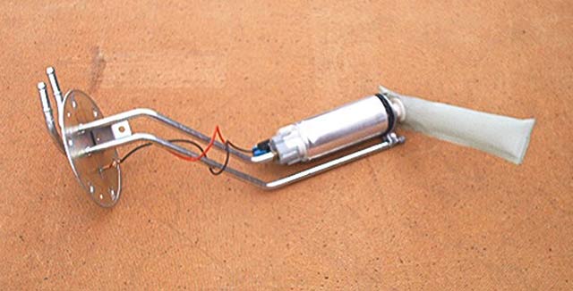
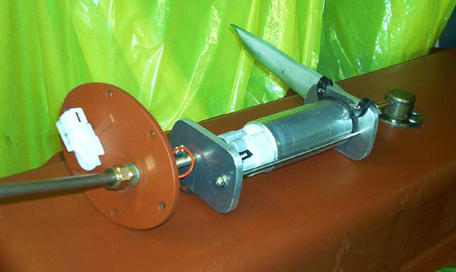
The original Cooper pump unit
I had a few options: I could use the Estate tank which I had bought new many years ago and buy a suitable out-of-tank pump unit, drawing fuel from the original feed line and add a return pipe and vent. I discounted this due to not having much space and difficulty finding a pump which would lift (as the pump would have to fitted above the fuel level) and then pressure feed to the engine. Another possibility would have been to mount the saloon tank inside the car at the rear in its normal position - this was rejected because it would encroach on the load space at the rear, as well as looking unsightly - never mind probably having to build a firewall for Mr MOT man. I decided to go down a third route, which involved much more work than all of the others but it looks no different from the original installation. The forward face of the estate tank has one flat section on the left side big enough, I reasoned, to fit my own modified in-tank unit, cannibalised from the original Cooper set-up.
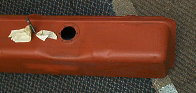
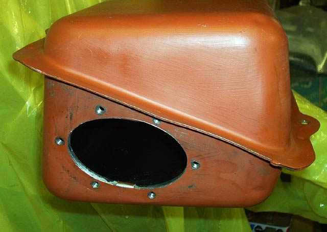
The proposed site is to the right of the hole for the sender unit and close to the top flange.
I thought for some time about the best way to fix this new unit and settled on a backing ring inside the tank with the front plate bolted through the tank wall into this ring. It couldn't be round, as I would never get it into the tank, so the next safest was an ellipse. I constructed an elliptical ring with the major inner distance greater than the minor outer distance, so that I could feed the ring into the tank to secure it. The minor distance had to be large enough to accept the pump unit and gauze filter.
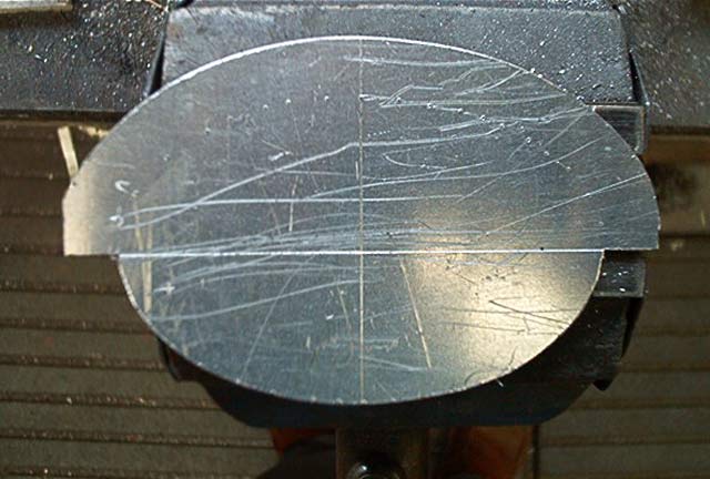
This is the template for the inner and outer shapes. Yes, there is a bit missing at the end - it was the largest piece of scrap I had to hand - so I fiddled the end curve a bit.
From an ease of manufacture point of view, it is far easier to make both curves as external ones, rather than beat yourself with birch twigs and produce an internal curve, involving more chain drilling and cutting, just for the template! So the pic shows the outer profile above the inner.
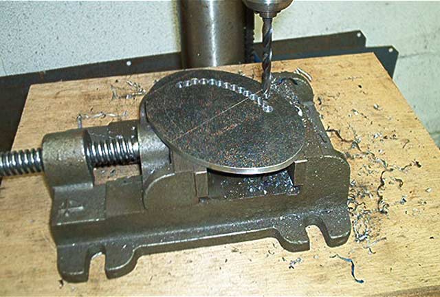
Chain drilling the internal profile.
In this case the job was large enough to be hand held on the vice, which makes positioning for the next hole easier. I used a drill of about 6mm diameter, so that it had enough strength to be 'persuaded' into another position if it looked too close to the line or the previous hole. 6mm is also small enough to snap if anything grabbed, to prevent me being spun around the shop with my boots banging on the freshly painted walls!
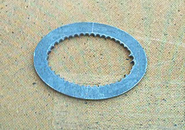
The pump plate securing ring - just needs the internal shape cleaning up now and then the threaded securing holes putting in.
The pipework also needs to be modified, both within the tank and externally. For the internals I have made up some of the parts on the lathe from brass. These have generally been silver soldered to the pipework and will be attached in the same way to the pump mounting plate. I will have to make a little vent tower which will be attached to the tank top and must protrude through the rear floor space and back out under the car to the carbon canister mounted under the front wing. The fumes from the tank (now fitted with a non-vented cap) are released into the carbon can when the valve on the bulkhead is opened by the ECU.
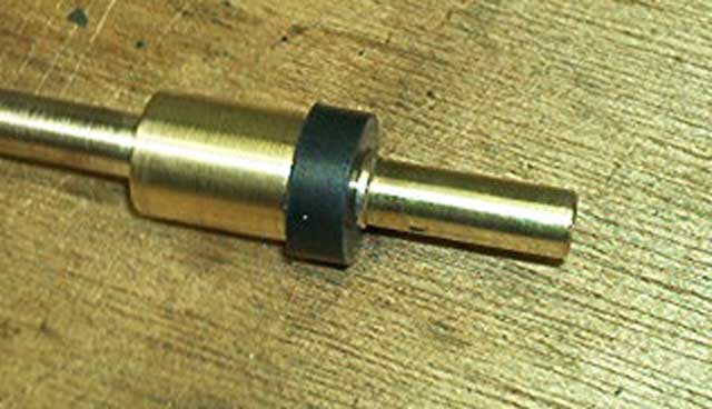
This is the pump outlet pipe, made on the lathe (and the original rubber seal fitted), which will eventually be fitted through the pump mounting plate.
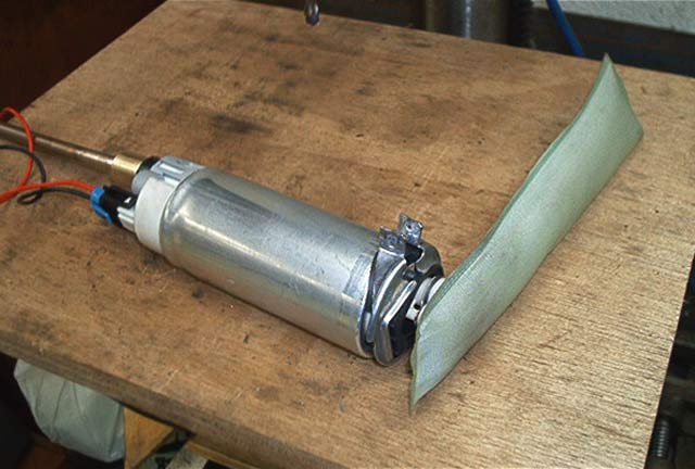
The pump - removed from the original pipework - now requires brackets to clamp the outlet and return pipes
The installation of the fuelling system is now nearing completion with the vent tower being the last part to be made. I did this on the lathe from a piece of scrap brass. There is a backing ring inside the tank (also in brass) which was fitted through the larger pump hole and held in place with Sikaflex. This ring has threaded holes (M5) spaced around a circle, so that the vent itself can be secured to the top of the tank, with M5 button headed allen screws in stainless, into the backing ring. I loosely packed the space inside the vent tower with stainless wire wool to prevent any fuel 'sloshing' up into it and then being carried along to the carbon canister.
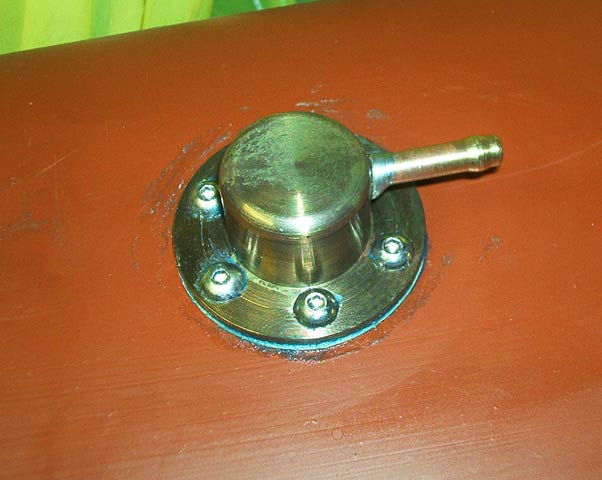
The vent tower secured to the tank top
The
pump unit is now ready to fit to the tank after many trials to ensure that
nothing would foul any other component (vent, fuel gauge sender or tank body
installation) I also tested the sender unit to check for correct operation
against the Cooper instrument. The original idea of fitting the pump in
the front face of the tank has now been changed as the whole assembly of pump,
pipes and brackets was making it rather tight for space. The next best
alternative is in the opposite end of the tank. I took the plunge and this
is now fully installed.
The
pump has also been tested on the wiring on the car to check that it runs for 2
or 3 seconds when the ignition is turned on and continues when the engine is
cranked - all was well in that department too.
I
had to keep the pump inlet as low as I possibly could, within the tank, to give
as much range to the already rather small fuel capacity. To this end, I
fitted a couple of rubber blocks to the lower edge of the pump clamp, and these
sit snugly on the floor of the tank, hopefully to prevent vibration. All
of the pipes, which I made myself from 'Kunifer' tubing, have a small olive
sweated on to the outside. These prevent the pipe from being forced off
under pressure, as the clip would have to come over the 'bulge'. Fuel is
returned to the tank via the original feed port, for which I had to make a union
nut and pipe fitting, as they are now no longer available.
The completed pump installation laid out on top of the tank showing the rubber buffer blocks wire-locked onto one of the alloy clamp brackets.
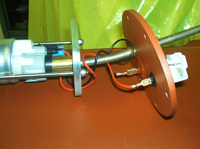
So that I could use the original quick-release wiring connector, the connector block has also been salvaged from the Cooper pump plate. This meant having to silver-solder a home made 'Lucar' type spade connector to the new oval pump plate and another to the inside of the plate to fasten the wiring to. This can be seen better in the following picture. The peculiar bends and angles on the pipe were done by experiment until I got the pump just where I wanted it
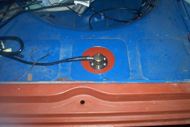
This is the final resting place for the injection unit pump. The tailpipe of the exhaust runs close by, so I will have to make up an aluminium/fibre type heat-shield to keep things separate.
The
vent tower needed a hole in the rear floor, under the access board for the spare
wheel, but this will not be visible and means that the pipe-work from it can also be
concealed.
The next job will be to refit the tank and exhaust and start the engine. It did run when I tested it in the crashed Cooper (18 months ago), but the idle air control valve (IACV) was smashed and letting in air, so it was revving too much (it would have screamed it's head off if I had let it!). I replaced the IACV, so it will be good to hear it on tickover this time. There is a spark at the right time and compression, so with some metered fuel all should be well. All of the brakes are bled and the clutch is working, so the Clubman Estate Shell, will finally move under it's own steam, for the first time in my 20 year ownership!
Sunday 15th September 2002
Well the big day arrived at last - with everything fitted and double checked and only one gallon of best unleaded in the tank, in order to find the minimum fuel level it will work with, I switched on the ignition and let the pump run for its normal 3 second prime, switched off and waited 10 seconds, re-primed and the pump started pumping fuel. I repeated this once more and then tried the starter - and bingo, it started up straight away. I didn't run it for very long as there is no water in yet - until I fit the heater unit - so it was on cold start mode and the ECU would get confused without a changing signal from the water temp transmitter. The tappets were a little noisy, but with only 5000 miles showing, they have never been adjusted since leaving the Factory.
I now need to tidy things up a bit and sort out the rear door and side windows, in readiness for an MOT, before pulling the whole lot to bits again to paint the shell in Rover 'Nightfire'